Basic Motor Control
The aim of this tutorial is to get a motor turning with your kit.
To complete this tutorial, you’ll need the following items from the kit:
- A charged battery
- An assembled kit according to the assembly guide
- A small (5mm) green CamCon connector to plug the motor into the Motor Board
- 2 lengths of wire for your motor
- A small slotted/flat blade screwdriver (for the CamCon screws)
And additionally you will need to provide the following:
- A motor (see specification below)
- A soldering Iron
- Some solder wire
- Wire strippers
Before continuing with this guide, if you have yet to setup your kit, first follow the instructions on the kit assembly page.
Motor Specification
There is a certain specification the motor(s) you use must meet. The criteria are as follows:
- 12V motor
- A stall current of less than 10A (this is the maximum current a motor will draw when it can’t turn)
Connecting a Motor
To plug the motor into the kit, you’ll need to solder two wires to the terminals on the motor, and connect the other ends to the CamCon connector.
Like so:
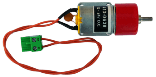
This motor should then be connected to motor 0 socket on the Motor Board. To see which output is number 0, look at the Motor Board page.
Adding the code
The following sections will lead you through running some code on your robot which will cause your motor to spin. By combining these examples you should be able to achieve movement with your robot.
Forwards & Backwards
To start off with, we’ll make a motor move forwards, then backwards, and then repeat.
The way we control motors is by providing a number between -1 and 1 to describe its power and direction.
As a first example:
from sr.robot3 import Robot

robot = Robot()

while True:
    robot.motor_board.motors[0].power = 0.5
    robot.sleep(3.0)

    robot.motor_board.motors[0].power = 0
    robot.sleep(5)

    robot.motor_board.motors[0].power = -0.5
    robot.sleep(3.0)

    robot.motor_board.motors[0].power = 0
    robot.sleep(5)
The first few lines in this example are repeated throughout the docs, they import our sr.robot3 library and then create our robot.
The line:
robot.motor_board.motors[0].power = 0.5
sets the target power of the motor connected to output 0 to 50% forwards.
Equally, the line:
robot.motor_board.motors[0].power = -0.5
will put the this motor into reverse at 50% power.
Finally setting the power to 0 will output no power and stop the motor.
So, if you put the above code on your robot, you should be able to see a motor spin forwards, stop, spin backwards, stop, and then repeat.
If you find that the motor doesn’t turn when you run the above code, check that you’ve got all the cables connected to the right places, in particular note that the Motor Board has two outputs.
For a comprehensive reference to the motor object, see the sr.robot3 module’s Motors page.
Changing the Speed
Now we’re going to modify the program to ramp (go from 0% to 100% slowly) the speed of the motor. Our aim is to do the forwards and backwards bit (as above), but, instead of setting the power to a fixed value we will gradually increase the power from 0% up to 50%, then back down to 0%.
Here’s the code:
from sr.robot3 import Robot

robot = Robot()

while True:

    # ramp from 0% to 50%
    for pwr in range(0, 60, 10):
        robot.motor_board.motors[0].power = pwr / 100  # Convert from percentage
        robot.sleep(0.1)

    # Drive at 50% power for a second
    robot.sleep(1)

    # ramp from 50% to 0%
    for pwr in range(50, -10, -10):
        robot.motor_board.motors[0].power = pwr / 100  # Convert from percentage
        robot.sleep(0.1)

    # Stop for a second
    robot.sleep(1)
You have seen most of these lines of code in the previous example but we have now added a for loop.
The for loop accepts anything that has multiple items that Python can step through to get multiple values.
One example of this is a list, which when printed appears in square brackets like so: [1, 2, 3].
This is called iteration.
For a comprehensive introduction to to lists, have a look at this tutorial.
The for loop will iterate over the list, taking each element in turn and making it available in the loop.
Here’s an example:
for i in [1, 2, 3]:
    print(i)
The above would output:
1
2
3
Then there’s the range() function.
The range() function returns a sequence of numbers.
The function has three forms that take one, two or three arguments to describe what the sequence of numbers should be.
The general format is:
range(start, stop, step)
- start
- The value to start your sequence at
- stop
- The value which stops the sequence if the next step passes or equals this
- step
- The value which is added on each step of the sequence
If only one argument is provided, this defines the stop point. The other two arguments are set to default values, which is a sequence starting at 0 with a step size of 1.
For example:
range(5) # [0, 1, 2, 3, 4]
If two arguments are provided, then these represent the start and stop with the step being set to 1.
For example:
range(2, 6) # [2, 3, 4, 5]
Taking range(0, 60, 10), as an example of all three arguments:
Starts at 0, going up in steps of 10, for all values less than 60.
range(0, 60, 10) # [0, 10, 20, 30, 40, 50]
Putting all of that together; in the motor control example we iterate over that sequence of numbers setting the motor power to each of those values in turn, with a delay of 100ms between. This will give a slow ramp (~500ms) rather than a step in power straight to 50%. You might want to run the code on your kit to see if it does what you expect it to.
Next Steps
From here, you should be able to make your robot move about. See if you can make your robot drive forwards to a given point, stop, turn around and then return to its starting point.
You might also like to see if you can make the code example above more concise by creating functions for different types of movement, such as moving and turning. This tutorial is good if you want to learn about how functions work.