Servo Board
 The Servo Board can be used to control up to 12 RC servos.
Many devices are available that can be controlled as servos, such as RC motor speed controllers, so these can also be used with this board.
The Servo Board can be used to control up to 12 RC servos.
Many devices are available that can be controlled as servos, such as RC motor speed controllers, so these can also be used with this board.
You can control the state of each servo output from the Servo Board API.
Board Diagram
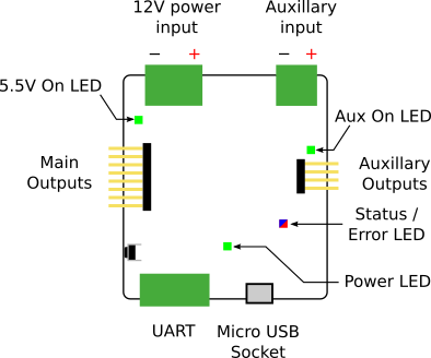
Indicators
| LED | Meaning | Initial power-up state |
|---|---|---|
| Power | The board is powered over USB. | On |
| 5.5V On | There is 5.5V power on the board. This usually indicates that the 12V connector rail is powered. | Off |
| Aux On | There is auxiliary power on the board. | On |
| STATUS|ERROR | Blue when the board has successfully booted Solid pink if 12V power is lost |
Blue |
Connectors
There are 8 servo connections on the left-side of the board (numbers 0-7), and 4 auxiliary outputs on the right (numbers 8-11). See the labels on the board (also visible in the photo above) for how these numbers map to the outputs.
Servo cables are connected vertically, with 0V (the black or brown wire) at the bottom of the board.
For the servo board to operate correctly, you must connect it to the 12V power rail from the power board. A green LED will light next to the servo board 12V connector when it is correctly powered.
Auxiliary outputs
Servo outputs 8-11 are supplied from the separate auxiliary power input. If you want to use these ports the power has to be connected to either the a 5V or 12V output of the power board.
Case Dimensions
The case measures 68×68×21mm. Don’t forget that the cables will stick out.
Servo Control
For an RC servo the angle of rotation is determined by the width of an electrical pulse on the control wire. This is a form of pulse-width modulation. (PWM) A typical servo expects to see a pulse every 20ms, however this can vary from servo to servo.
The Servo Board is able to precisely control the duration of the pulses sent to servos (based on the values you configure using the Python API), within the ranges in the table below.
Specification
| Parameter | Value |
|---|---|
| Number of servo channels | 12 |
| Nominal input voltage | 11.1V ± 15% |
| Output voltage | 5.5V |
| Maximum total output current 1 | 10A |
| Default pulse range | 1ms — 2ms |
| Maximum pulse range | 0.5ms — 4ms |
| Pulse precision | 5µs |
Designs
You can access the schematics and source code of the firmware on the servo board in the following places. You do not need this information to use the board but it may be of interest to some people.
-
If the auxiliary input is connected, outputs 8-11 have an independent maximum current. ↩