Motor Board
Note
The schematic has motors 0 and 1 reversed from the silkscreen and code.
Note
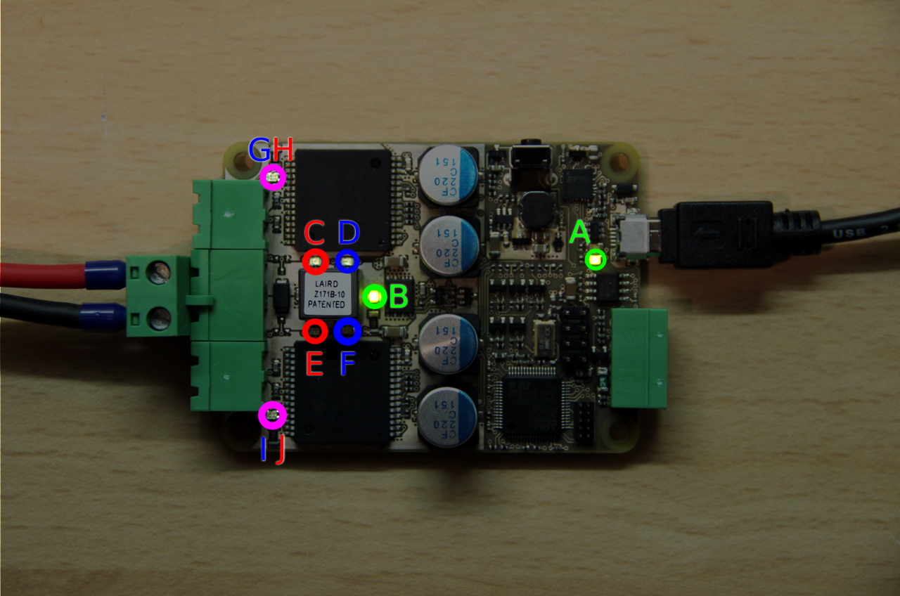
The boards pictured above is an early prototype and may differ from the current boards, it is only used to display the locations of the LEDs.
The motor board contains an isolation barrier to avoid ground loops. This means power must be provided to the 12V input and USB. The USB only powers up the USB-serial adapter and not the microcontroller, as such without 12V power, the USB port will appear but will not respond to any communication.
Motor Board LEDs
- A (DS1/DS6 - green/red)
- green is lit when USB or UART power is present
- red is lit when there is USB activity to the USB-UART IC.
- B (DS7 - red/green)
- green is lit when there is 12V present in the correct polarity on 12V input
- red is lit when the 12V input has incorrect polarity
- C (DS2 - red)
- lit when the motor 1 driver has detected a fault. This is probably short-to-VCC or short-to-GND.
- D (DS3 - blue)
- lit when the motor 1 is drawing over 5 amps (50% load)
- E (DS4 - red)
- lit when the motor 2 driver has detected a fault. This is probably short-to-VCC or short-to-GND.
- F (DS5 - blue)
- lit when the motor 2 is drawing over 5 amps (50% load)
- G/H (DS9 - red/blue)
- blue is lit when motor 1 is set to move forward
- red is lit when motor 1 is set to move backward
- I/J (DS8 - red/blue)
- blue is lit when motor 2 is set to move forward
- red is lit when motor 2 is set to move backward