Servo Board
Note
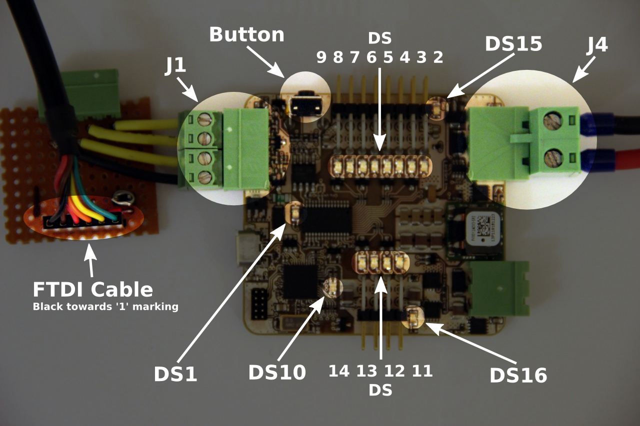
The boards pictured above is an early prototype and may differ from the current boards, it is only used to display the locations of the LEDs.
The servo board contains an isolation barrier to avoid ground loops. This means power must be provided to the 12V input (J4) and USB. The USB powers up the microcontroller so the board can be connected to without 12V present. The 12V then drives an isolated output expander that controls the servos and a high current regulator that provides 5V for the servo power. This will only power servos 1-8.
To use servos 9-12 power is applied to the AUX header. This power is applied to the servos directly so do not apply 12V to the AUX header when using 5V servos.
Servo Board LEDs
- DS1 - green
- lit when 5V is present from either the USB or UART header, this is connected to the 3.3V regulator output so shows it is functional as well.
- DS2-9 - blue
- lit when the corresponding servo is enabled. Setting the servo to any position will enable them. These will light even when the 12V power is not present.
- DS10 - red/blue
- blue is lit as soon as the firmware finishes initialisation.
- red is lit while I2C communications are failing. This occurs while 12V is not present.
- DS11-14 - blue
- lit when the corresponding servo is enabled. Setting the servo to any position will enable them. These will light even when the aux power is not present.
- DS15 - green
- lit when 12V is present and the correct polarity, this is connected to the 5.5V SMPS output so shows it is functional as well. If the 12V input is wired backward this will not light.
- DS16 - green
- lit when an input is provided to the auxiliary header.